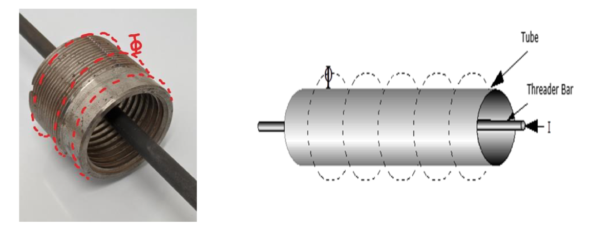
Threader Bar (TB)
Sometimes known as the central conductor technique, although the conductor need not always be central.
The object being examined must be of hollow section and access must be available to both ends. Providing these limitations are met, then an electrical conductor - typically made of brass, copper or aluminium - is threaded through the bore, or aperture, and a current passed through it. (NB. When using a nonferrous threader bar, the field in a ferrous cylinder (test piece) would be greater than that in, or surrounding, the threader bar.).
A blind threaded bar C.F. technique could be applied to hollow parts with only one open end. However, several specifications do not allow this due to the increased difficulty ensuring good internal electrical contact.
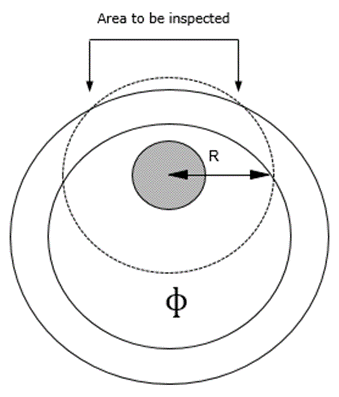
This sets up a circular field in the surrounding ferromagnetic material in a direction at 90° to the current flow, therefore, the technique is used for detecting discontinuities parallel to, and up to 45°, of the current flow, e.g. longitudinal pipe discontinuities.
BS EN ISO 9934-1 quotes for central conductors, the same values as current flow will be applied, whilst non-central conductors will be assessed, measuring the tangential field strength. Separate values will be applied for the inside and outside surfaces.
The conductor may be located centrally to the specimen, but on larger diameters the conductor is often placed to one side to ensure sufficient flux strength and the test piece rotated to allow for surface inspection. Alternatively, two conductors may be used on larger diameter test pieces. When a current is passed through conductors, such as a threader bar, one of which is magnetic the other non-magnetic, the field surrounding them would be the same.
The threader bar technique is ideal for the testing of ring like specimens, especially because numerous samples may be tested at the same time; lengths of pipe may also be examined by this technique. On site work, this technique is not widely encountered, but could be modified by using a flexible cable instead of rigid conductor.
Threader bars are usually insulated to prevent damage to the test piece, and to electrically shield the bar. When using a threader bar that is not covered with insulating material, care should be taken to ensure that components in contact with the threader bar cannot touch any part of the magnetic equipment at earth potential.